Datsun 510 Blog
I blog about everything. Even my car.
Jason Gray's Datsun 510 Spec Sheets (not mine)
Engine Spec Sheets | Transmission Ratio Sheets | 280zx Struts | L-series Turbo | Electronic DistributorWiring Diagrams
Externally Regulated Alternator | Internally Regulated AlternatorOther Useful Automotive Resources
ratsun.net | the 510 realm | carbibles.com | Hainz's L-series teardown/buildup | DIY Air Fuel Meter | CR Calculator | Wheel to Crank Calculator | HP calculator | Intake runner calculator |GAUGE CONTROL MODULE
2021-05-13 09:30:46
by: jovial_cynic
by: jovial_cynic
I started this project because I wanted to see if I could drive a few gauges I owned using the AtTiny85 microcontroller and the sensors that came with my car. In particular, I wanted to display the values for the following:
- Fuel Level
- Oil Pressure
- Coolant Temp
- Fuel Pressure
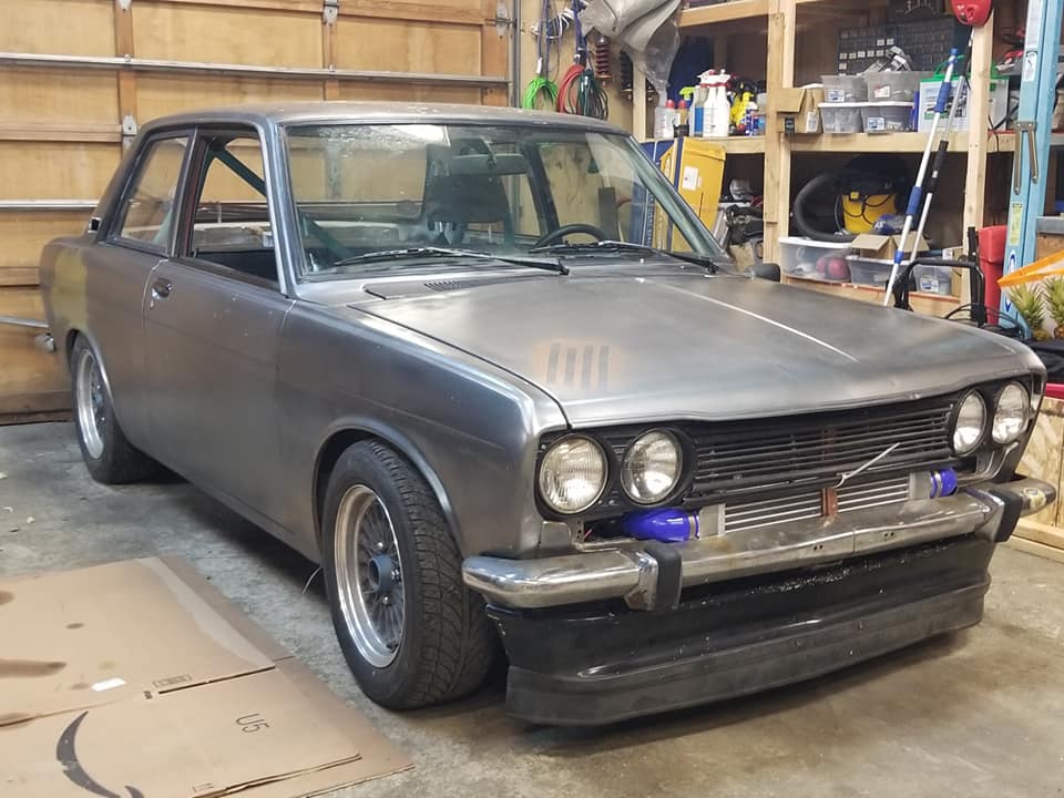
Because my Datsun 510 is entirely custom, it means that I don't have any of the original gauges. Even if I did, I don't have the original engine, so the sensors wouldn't play nicely with the factory gauges anyway. A custom solution seemed to make sense.
The first step was to get the resistor value ranges for the sensors. Most sensors have some kind of increasing or decreasing amount of resistance, depending on what is being measured. My fuel tank has a float that raises an arm, and as the fuel level decreases, the sensor resistance increases.
In this specific example, the fuel level sensor has a range of 10ohms (full) to 80ohms (empty). From everything I've read about the stock Datsun 510 fuel level sensor, it's a fairly linear relationship. That would mean that 38ohms is roughly half-full.
The next step in this project is to create a voltage-divider circuit.
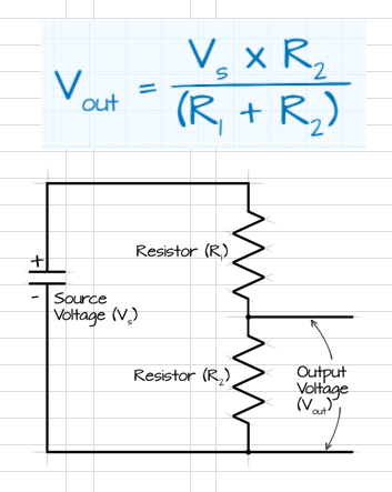
Basically, this allows you to read a voltage output that will vary, depending on the change in resistance of either one or both of the resistors. If I use a fixed 100ohm resistor in the circuit and push 5v through it, the circuit will generate an output that can vary between 0v and 5v, and that will give me the analog voltage data I need to drive my gauges.
Just for kicks, here is the data and graph that I set up in Excel for the fuel level sensor voltage divider circuit.
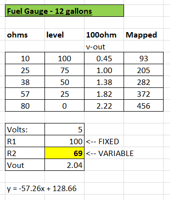
This shows the ohms, the fuel level (in percentage) in the gas tank, the voltage output from the voltage divider circuit, and the 10bit value that the AtTiny85 will see when it reads the 0-5v signal. Below that is my little voltage divider circuit calculator that I used so I could see what the voltage would be, given any ohm reading between 10 and 80.
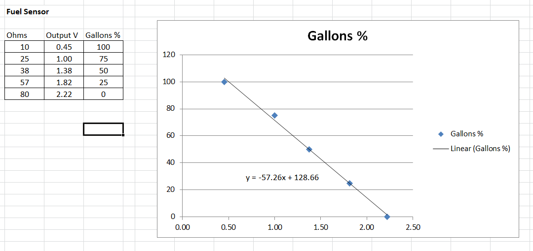
This graph has the same basic data, but shows it in graph format. Excel has a built-in feature that lets you see the slope (or polynomial) formula (y = -57.26x + 128.66) based on the plots on the graph, which will prove to be VERY useful later.
You'll notice that I'm using percent-full for my data. I could have used actual gallons, but because fuel gauges are really about showing that you need to go to a gas station, it doesn't actually matter how many gallons the tank can hold. That's not terribly useful data for my purposes, so I went with percent-full instead.
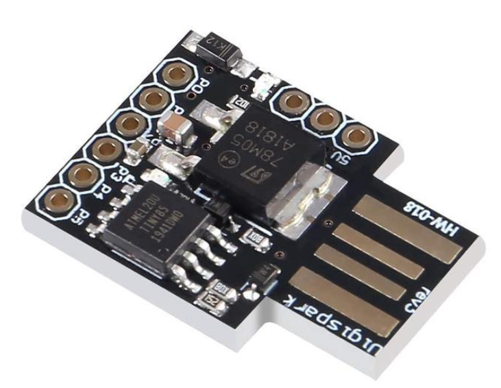
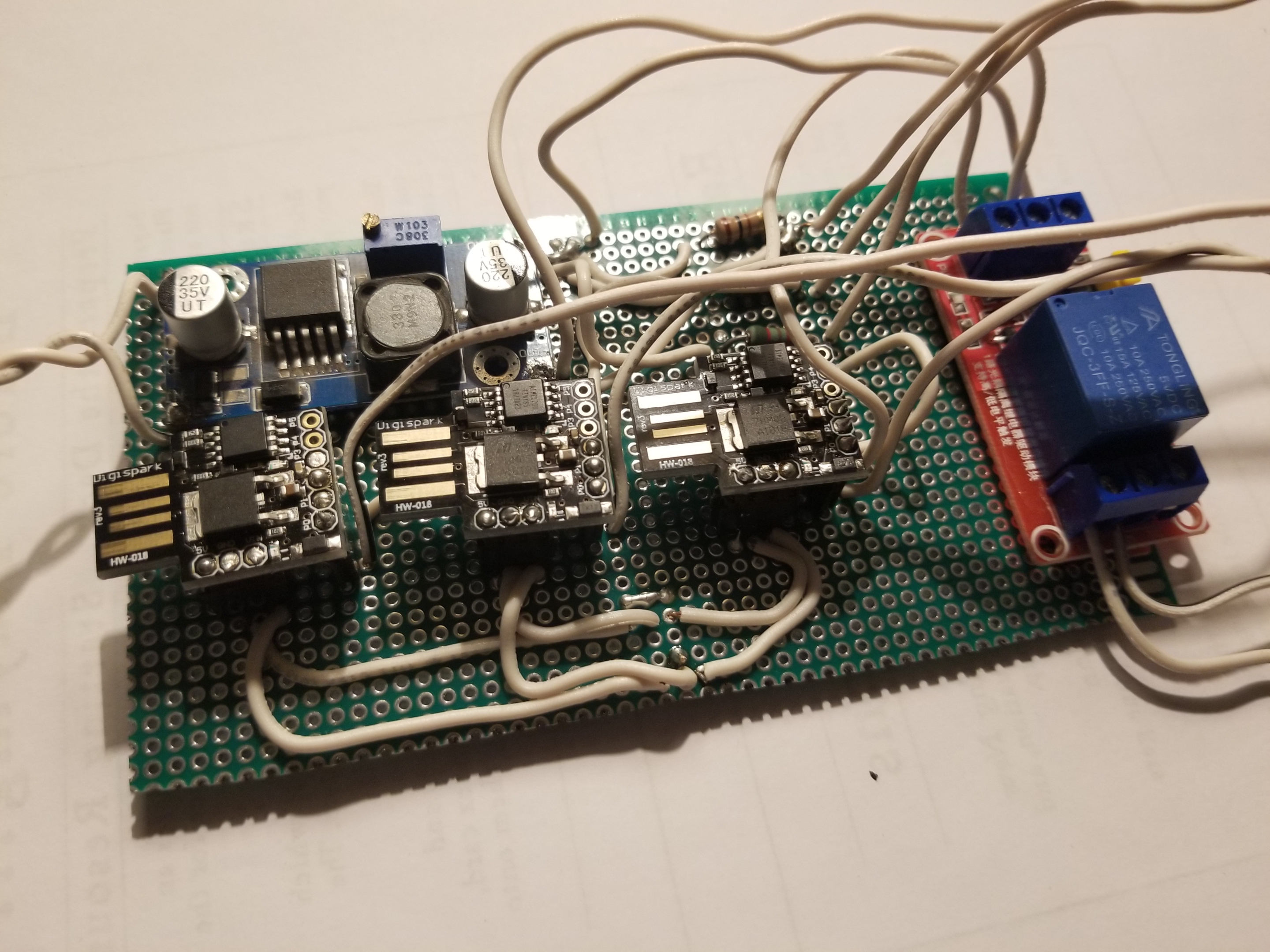
So, armed with all the data I need, I moved onto the programming the AtTiny85 to do my work. Well, three AtTiny85s. I have three of them for this project, and they're powered by a buck-converter that's taking the 12v car power and bringing it down to 5v for the AtTiny85s and the gauges. If you don't know, the AtTiny85 is like a smaller, less-powerful Arduino. You can use the same basic code, although there are some hardware specific features that aren't available. But for this project, it's perfect.
On the AtTiny85, I'm using the analog input pin (A0) to read the voltage coming in from the voltage divider circuit and running that data through the following processes:
1. Read the voltage into pin A0. That data comes in a 10-bit format, so to convert the value into something that makes sense, you divide 205 by the voltage reading, and that gives you the actual voltage.
float sensorValue = analogRead(A0);
sensorValue = sensorValue / 205;
So, here's an example: Let's say that the resistance from the fuel tank reads 38ohms. If you run that through the 100ohm voltage divider circuit and push a 5v source through it, you end up with a 1.38v output. That shows up as 283 on the analog-to-digital converter, so divide that by 205, and that gives you 1.38v.
As a side note, I'm only doing the "divide by 205" to make my code easier for me to follow. I want the next formula to be a "voltage -> percent-full" value, so I did this for convenience. It's probably cleaner to keep the original ATC value and do the math that way, but I wanted to do it this way.
The next step is to run the voltage through the slope formula from before: y = -57.26x + 128.66
This part of the code looks like this:
percentFull = (-57.26 * voltage) + 128.66;
So, if you put the 1.38 volts into the formula, you get:
(-57.26 * 1.38) + 128.66 = 49.64
Well, 49.64 is basically 50. And because my formula is designed to output a value between 1 and 100, we're showing a tank that's half-full. Or half-empty.
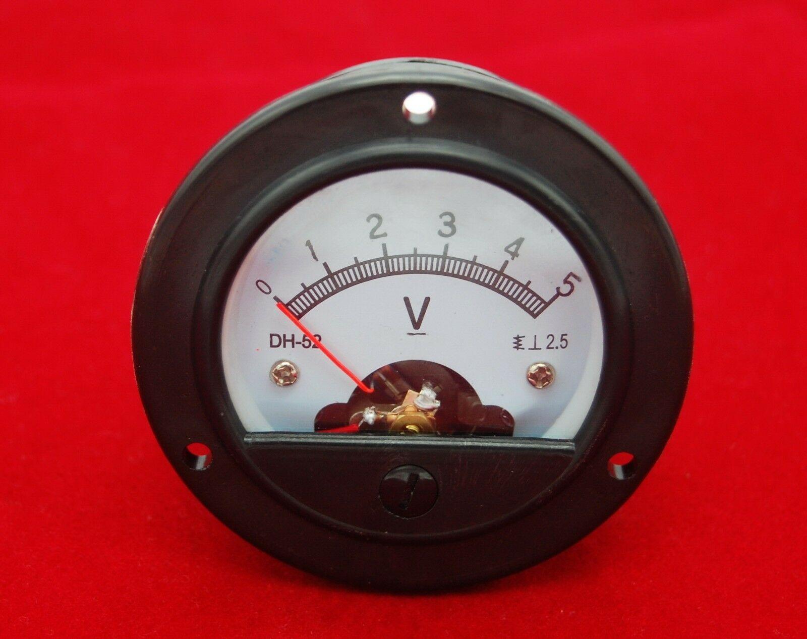
The next thing to do is to take the "50" value and make that output to a gauge somehow. The AtTiny85 has a pulse-width modulator (PWM) output based on a 0 (no output) to 255 (constant output). As it turns out, 5v panel gauges treat PWM output a bit like regular voltage; PWM 255 = 5v on the gauge, and PWM 127 is about 2.5v on the gauge. Since I'm trying to make a value of 0-100 and output it to a value between 0-255, I use the map function:
pwmOutput = map(percentFull, 0, 100, 0, 255);
And then I send that mapped value to the gauge:
analogWrite(A0, pwmOutput);
That's really all there is to the fuel level sensor and gauge output.
The oil pressure is essentially identical, only the ohms range from 10 to 50, and rather than percent-full (which makes no sense on an oil pressure gauge), I'm outputting the actual pressure values (0 to 80PSI), with the target PSI being at 40. The voltage divider circuit is different due to the different resistors needed to make it work properly, and the slope formula is also different. Lastly, the map function will read 0 to 80, so that the target value of 40 ends up in the center of the gauge. That's an intuitive way to read the oil pressure, and I wish more gauges functioned that way.
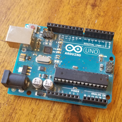
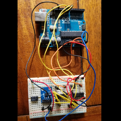
The water-temp has some of the same differences, but I'm adding one additional function to AtTiny85: once the water temp hits 200F, the microcontroller will send an "on" signal to a 5v relay module, which will flip a switch to turn on the 12v engine fan. This will prevent me from having to keep the fan running all the time.
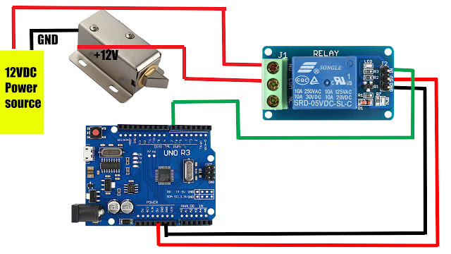
This is an image of the relay module hooked up to a traditional Arduino, but it works with the AtTiny85 the same way.
comments [0]
FUEL PRESSURE CONTROL MODULE
2021-05-13 08:52:48
by: jovial_cynic
by: jovial_cynic

Some Nissan engines use an odd technique for regulating fuel. When the engine is at idle, rather than lower the pulse-width modulation (PWM) signals to the injectors by changing the output signals from the ECU, they actually decrease the voltage going to the fuel pump to lower the fuel pressure. That way, the injectors continuing firing off at the "base" frequency, but there's just less fuel pressure behind them.
I did an engine swap into my 1971 Datsun 510, and I didn't know that my replacement engine (1991 SR20DET) was supposed to have this weird Nissan fuel pressure control module (FCPM). It didn't come in my box of parts, so I just constantly battled a fuel-rich condition whenever I let off the throttle.
Anyhow, I learned about this FPCM and poured over the wiring diagram to figure out exactly how it worked. Apparently, when the engine is off-throttle, a signal from the ECU (pin #105, in my case) outputs a 12v+. When I step on the throttle, pin #105 outputs nothing. So... I figured I could wire in a relay from that 12v source, and run the power to the fuel pump through a heap of high-watt resistors - just enough to drop the voltage down to 10v, which is perfect for correcting the air-fuel ratio. But, when I get on the throttle, the relay kicks over and reroutes power straight to the fuel pump.
And... voila! It works!
comments [0]
ROLL CAGE IN
2021-03-13 20:21:31
by: jovial_cynic
by: jovial_cynic
Around this time in 2019, I managed to pick up a roll cage for the Datsun 510 for a whopping $50. The feet were cut off, so I had to do some work to get it welded into the car. Naturally, this means that the project just sat for a couple of years while I did other things.
Having moved back into a house, I decided that it was now time to get it done.
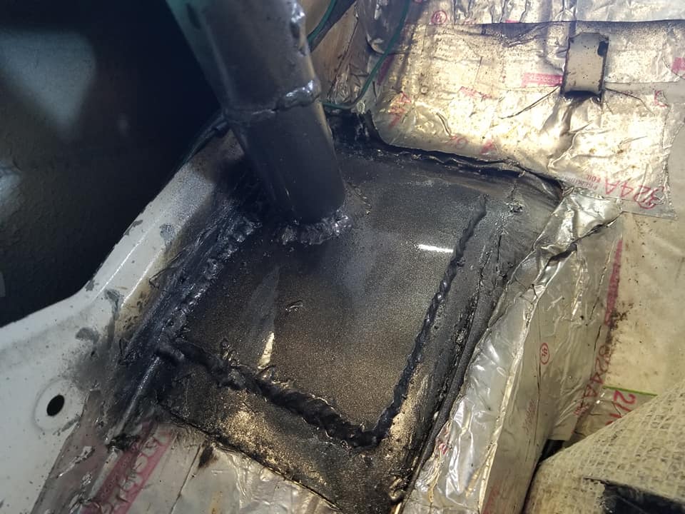
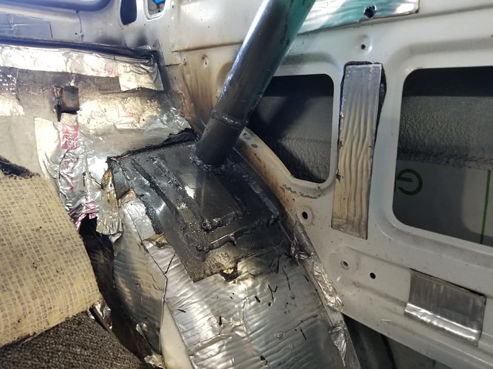
A couple of days of welding during my lunch breaks, I finally got it all safely welded in.
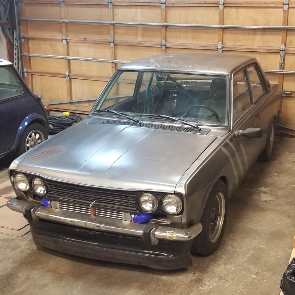
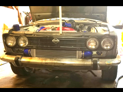
Here's a couple of exterior shots that make me pretty happy with my car.

comments [0]
Having moved back into a house, I decided that it was now time to get it done.
A couple of days of welding during my lunch breaks, I finally got it all safely welded in.
Here's a couple of exterior shots that make me pretty happy with my car.
comments [0]
510 TELEMETRY PROJECT
2018-05-30 08:46:55
by: jovial_cynic
by: jovial_cynic
It's been a while since I've posted on here about my Datsun 510. I think the last post was in March of 2016, although I've posted quite a few short posts and images on Facebook, Twitter, and Instagram. I'll probably spend some time going through all of those posts and copying the content here, so I have it on my own server.
Speaking of my server, I haven't posted much since my webhost updated their Perl server, so I had to go in and update a bunch of my code to even post!
Anyhow, I've done quite a bit on the 510 lately. Between upgrading all of my brakes (discs all around), fabbed up new intercooler plumbing, and finally dumping the R33 skyline gauge cluster, I decided that the next major project to tackle would be the big electronic project: the Arduino/Raspberry Pi telemetry and custom gauge cluster system. It doesn't sound like much, since I haven't seen many overly complex Arduino or rPi builds, but this has been a pretty significant undertaking.
The basic premise of this project is this:
Use the Arduino to pull data from no less than 16 sources. On a standard Arduino UNO, this is not possible; there are only 6 analog inputs. However, using the magic of multiplexing, there's a way to quickly poll multiple sources over a single analog input; with two 8-channel multiplexers, we get that 16, plus the remaining 4 on the board itself.
Once the data is pulled (either direct 0-5v values or values drawn from a voltage divider circuit), it is neatly organized into a (name:value) pair, and sent as plain-text serial data via USB into the Raspberry Pi. On the rPI, I'm using Perl/Tk to pull in that serial data and display it graphically on a custom instrument cluster as well as saving the data for future analysis.
And then all of that is displayed on a 9x5" LCD screen.
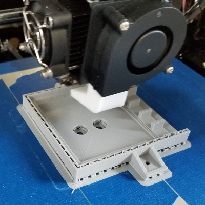
Easy, right? Well, then there's the whole project of packaging it all up. So, that's where the 3d printer comes in. I assembled an ANET-A8 3d printer, learned how to use Blender, and printed out some bits to bring it all together.
The first thing I needed to print was an enclosure for the LCD driver. It came as a PCB board attached to the LCD screen with a power supply line and a ribbon cable; boxing it up meant printing a custom enclosure that I found and modified on thingiverse.
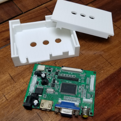
The model online didn't include a lid, so I used Blender to build one.
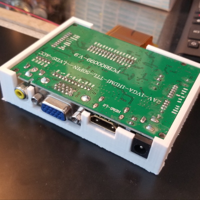
Fits like a glove.
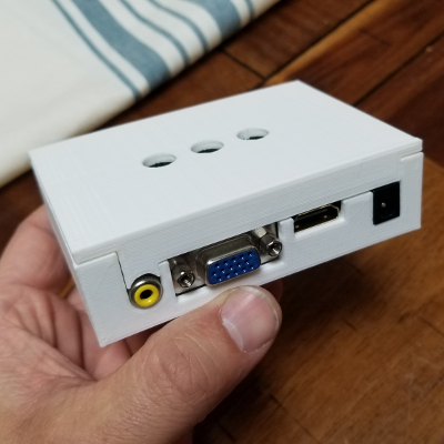
Perfect!
The next thing I needed to do was to figure out a way to mount the LCD. It's going to sit in the Datsun 510, so I can't just have it sitting on the dash. I printed these corner brackets, and they seem to work just fine. It's not beautiful, but it is very functional.
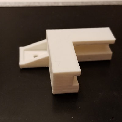
Again, using blender to design it. I've used the bracket in several of my 3d prints, as it's perfect for small screws.
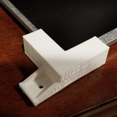
Fits the LCD screen. It's a little loose, but maybe I'm compensating for heat distortion?
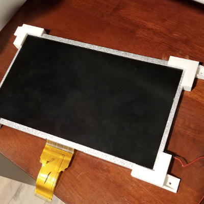
Test fit.
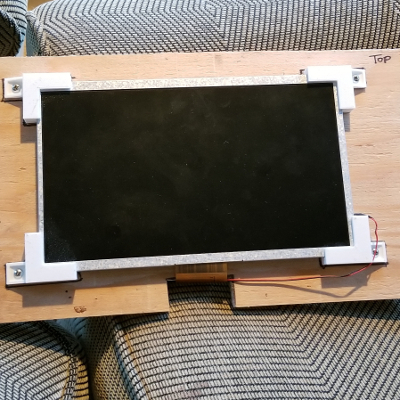
And screwed down to a piece of plywood.
The next project was to build a custom Arduino. Yes, you read that correctly. Because I have a need to take things apart and put them back together, I wanted to do one of those custom "minimalist Arduino" projects where I just use the atmega chip, a few resistors, a crystal, and some capacitors, and voila - homemade Arduino.
Here's an UNO. It's the one I used to test all of my code.
And here's the Arduino connected to the two 5041 multiplexers.
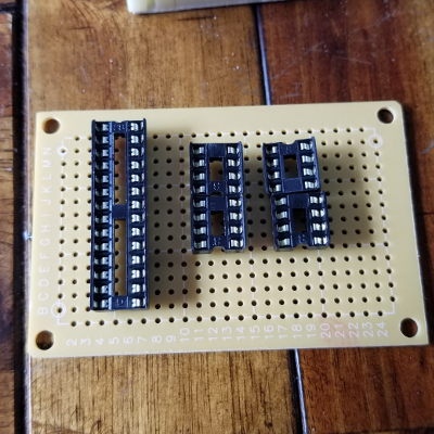
Perf board with the chip plugs. Always use these things; soldering down (and then trying to remove) a chip sucks if you have to re-orient later.
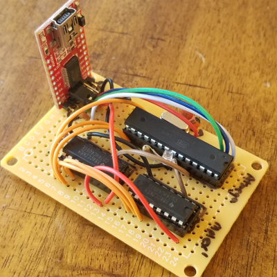
Here is my minimalist Arduino board, together with the two multiplexers and a USB interface board.
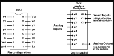
In case you're nerdy, here's the multiplexer pintout.
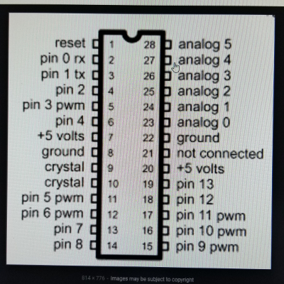
And here's the Arduino atmega chip pinout.
With 16 inputs, I didn't want a bunch of loose wires everywhere, so I decided to use some JST clips to organize my wiring. I couldn't find any 16-terminal JST plugs, so figured having 4 sets of 4 would work just fine.
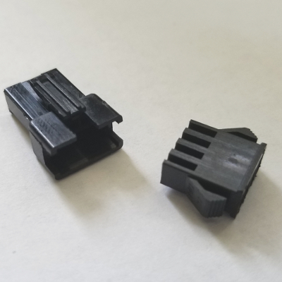
This is a 4-wire JST clip set.
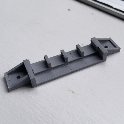
Not satisfied with having the clips dangling about, I did some test printing and built a holster for the clips.
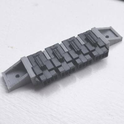
Perfect fit! However, this holster was just a proof-of-concept. I wanted to make sure they would fit properly so I can build an Arduino housing model that would incorporate the design.
And here's a shot of the prototype of the Arduino housing. You can see the brackets that I've reused from the LCD clips, as well as the JST holster.
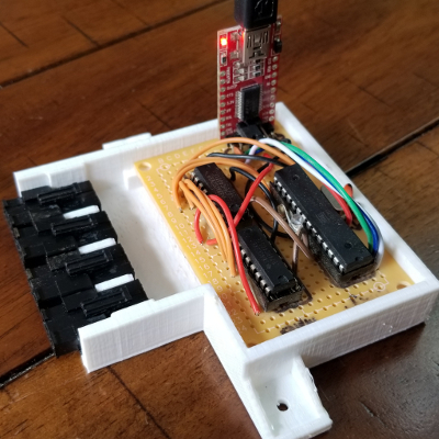
And the arduino+multiplexer perf board fits perfectly.
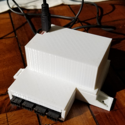
And here's a tall lid for the enclosure. In hindsight, I probably should have found a USB connector that could lay horizontally so I didn't have to make the box so tall.
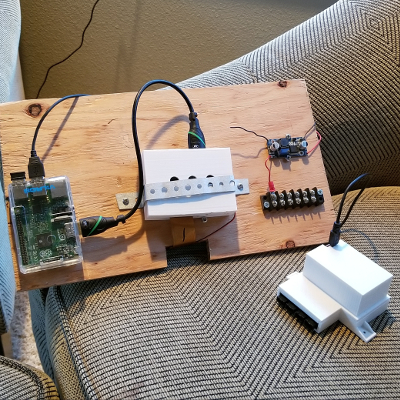
At the time of this writing, I'm still trying to figure out how to pull it all together neatly. Right now, I've just thrown it all onto a piece of plywood. It works, but this is not likely the final product.
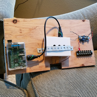
On the left is the Raspberry Pi, connected by HDMI to the LCD driver housing in the center. On the right is another project - it's going to be the power supply for the whole thing. The LCD screen requires a 12v power supply - no problem. The Datsun 510, like most cars, has a 12v battery. I'll need to include a voltage regulator circuit to address voltage spikes and reversals, since that'll destroy my electronics. The Arduino and the rPi, on the other hand, only need 5 volts, so I have a switching converter to create a 5v power supply. This is particularly useful because several of my sensors need a 5v source as well: the MAP sensor (boost sensor), for example. The Arduino also accepts 0 to 5 volt inputs, so building voltage divider circuits from here is also important.
Here, I have the Arduino hooked up and ready to go.
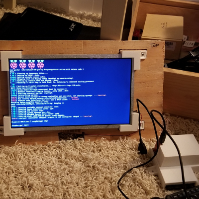
The Raspberry Pi is loading...
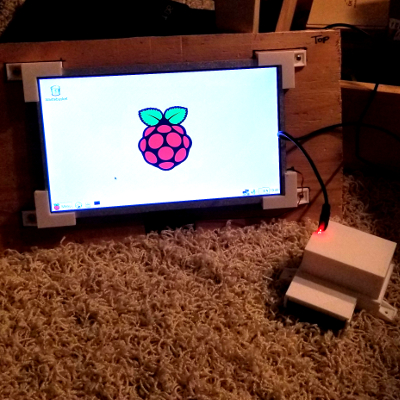
And we're in X-Windows on the Raspberry Pi.
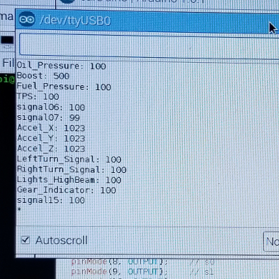
And here's the Arduino IDE serial monitor, and it's correctly reading the values from the rPi and multiplexers. There's no sensor data at the moment, so all the inputs read high. They would read low if they were grounded, and they would read correctly if they were connected to sensors properly.
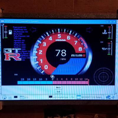
And lastly, here's the custom gauge cluster I coded. The tachometer is from an image of a Nissan Skyline tach; the Fuel Level, Oil Pressure, and Water Temp gauges were just cobbled together from some generic images online. I drew up the Boost gauge, and it may change to fit the scheme better. Once I have some data coming in from my accelerometer, I'll have the "g-force meter" working properly as well. This is all done within Perl/Tk.
I ended up using a different virtual gauge cluster for the next phase of the proof-of-concept, and it turned out quite well! It turns out that Chromium has a serial-communication plugin that works perfectly, and I was able to code this in javascript. Not that I prefer javascript over perl, but it is a little more intuitive.
End note: Due to wanting to simply drive the car and to get things done, I've changed directions on this project. However, I learned a lot during the coding and wiring, and I've applied some of the learnings to future projects.
comments [0]
SHEET METAL WORK
2016-03-29 15:50:54
by: jovial_cynic
by: jovial_cynic
Because I've become comfortable cutting up the Datsun 510 and welding it back together, I decided to try my hand at some panel repair.
A couple of years back, I tore apart the rear panel of my car to address a significant bondo issue. As in, there was too much of it, and it just needed to be removed. This time around, I decided to fix a portion of the rear passenger panel. This actually required a bit more work, because I had to fabricate the 510's signature lines.
Now, I could have bought a replacement panel from Futofab, and this particular piece would have only been about $100. However... I do like doing things myself and learning in the process, so... here we go.
Between my bead roller and some careful hammering, I got pretty close:
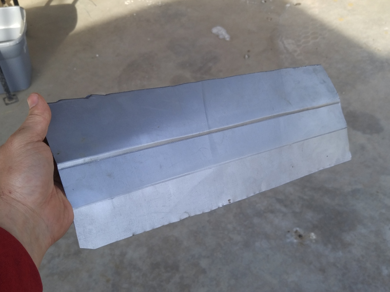
And here's the reason I needed to make that panel:

It's pretty amazing how much better this looks... and it's not even attached to the car yet. Having a straighter line makes a world of difference.

Here it is welded up. You can tell it's not perfect, but it's so much better, and I don't mind correcting the minor errors with a little bit of filler.

comments [0]
A couple of years back, I tore apart the rear panel of my car to address a significant bondo issue. As in, there was too much of it, and it just needed to be removed. This time around, I decided to fix a portion of the rear passenger panel. This actually required a bit more work, because I had to fabricate the 510's signature lines.
Now, I could have bought a replacement panel from Futofab, and this particular piece would have only been about $100. However... I do like doing things myself and learning in the process, so... here we go.
Between my bead roller and some careful hammering, I got pretty close:
And here's the reason I needed to make that panel:
It's pretty amazing how much better this looks... and it's not even attached to the car yet. Having a straighter line makes a world of difference.
Here it is welded up. You can tell it's not perfect, but it's so much better, and I don't mind correcting the minor errors with a little bit of filler.
comments [0]
2015-06-03: R33 CLUSTER IN THE SR20DET 510 2015-01-27: GAS TANK UPGRADE 2015-01-27: SR20DET FITMENT 2015-01-27: SR20DET RELAY BOX 2015-01-27: NEW SEATS 2015-01-27: FINGER CHOPPING FAN BLADE 2013-05-20: ADVENTURES IN BODYWORK 2012-12-02: BEAD ROLLER 2010-10-03: PAINT JOB RESULTS: GOOD ENOUGH 2010-09-27: RUSTOLEUM PAINT JOB 2010-03-20: JUST AN INCH 2010-02-27: SIDE SHOTS 2010-02-27: MORE ODDS AND ENDS 2010-02-20: ODDS AND ENDS 2010-01-30: DATE AT THE JUNKYARD 2009-12-02: JUNKYARD HEAVEN 2009-11-29: FISCH ART 2009-10-24: LIGHT AT THE END OF THE TUNNEL 2009-10-14: FIVE DEGREES 2009-10-12: DIY DYNO RUN 2009-09-29: FUEL PUMP SPACER 2009-09-27: ALL ABOUT TIMING 2009-09-12: TWO WIRES 2009-05-09: NEW KICKS 2009-04-26: BY THE SEAT OF MY 510 2009-04-20: DATSUN 510 PICTURES 2009-04-08: BACK ON THE ROAD 2009-03-15: MORE DRIPPING 2009-02-24: HERE A DRIP, THERE A DRIP 2009-02-17: NISSAN/DATSUN TRANSMISSIONS 2009-02-16: ENGINE AND TRANNY 2008-11-21: REAR WINDOW INSTALLED 2008-11-06: RING GEAR INSTALLED 2008-10-23: NEW ALTERNATOR 2008-10-23: PULLED THE RING GEAR 2008-10-20: PULLING THE ENGINE 2008-10-20: REMOVING THE ENGINE AGAIN 2008-10-18: MAKING IT SAFE 2008-08-05: RAT OF A CAR 2008-06-28: BANJO 2008-06-24: TINKERING 2008-06-19: CLUTCH MASTER CYLINDER 2008-06-17: ON THE ROAD AGAIN 2008-02-02: SPEED BLEEDERS 2008-01-27: DRIVING AROUND AGAIN 2008-01-26: THROTTLE CABLE 2008-01-26: TIMING SORTED OUT 2007-11-17: TIMING THE DISTRIBUTOR 2007-11-16: ELECTRONIC DISTRIBUTOR 2007-10-25: SMALL PROGRESS 2007-08-06: RADIATOR: THE CONTINUING SAGA 2007-07-30: WRONG ABOUT THE RADIATOR 2007-07-28: NO RADIATOR SWAP 2007-06-30: ACHIEVED IDLE 2007-06-23: BACKFIRE 2007-06-23: SHE'S RUNNING! 2007-06-22: COOLANT LINES 2007-06-17: SU CARBS INSTALLED 2007-05-14: LOTS OF PICTURES 2007-04-20: SU CARBS 2007-04-17: VACUUM LEAK 2007-04-15: EXHAUSTING EXHAUST WORK 2007-04-12: FLEX TUBE != EXHAUST PIPE 2007-04-11: AROUND THE BLOCK 2007-04-09: RUNNING SMOOTH 2007-04-09: SHE LIVES! 2007-04-06: WATER, WATER, EVERYWHERE! 2007-04-02: INCHES AWAY 2007-03-29: WHOLE LOTTA NOTHING 2007-03-17: CAR PORN 2007-03-08: ROUND AND ROUND WE GO 2007-03-04: PAPER 510 2007-02-28: PROBLEMS WITH EVERYTHING 2007-02-16: ELECTRICAL GREMLINS 2007-02-14: ENGINE INSTALLED. AGAIN. AGAIN. 2007-02-13: EARLY BIRD GETS THE CAR DONE 2007-02-08: COMPRESSION RATIO? 2007-02-05: STARTER ISSUE FINALLY RESOLVED 2007-02-02: EXTERIOR FRAME: RADIATOR SUPPORT 2007-01-30: PLANS FOR THE EXTERIOR FRAME 2007-01-29: MEASURE TWICE, CUT ONCE 2007-01-29: EXTERIOR FRAME TOO WIDE 2007-01-27: OUT OF BODY EXPERIENCE 2007-01-24: PREP WORK FOR SECOND INSTALL 2006-12-24: NEW YEARS PLANS 2006-12-01: PAINT? 2006-11-04: NEW CLUTCH KIT 2006-11-04: ROADSTER CLUTCH KIT 2006-10-05: BUILDER'S BLOCK 2006-10-02: CHOP CHOP 2006-06-05: THROWING MONEY AWAY 2006-05-06: TRANSMISSION MOUNTED 2006-05-05: MORE ENGINE WORK 2006-05-05: ENGINE INSTALLED 2006-04-30: ASSEMBLY NEARLY COMPLETE 2006-04-14: NEW TIMING CHAIN 2006-04-14: CHEAP TIMING CHAIN 2006-04-13: WORKING ON THE CAR 2006-04-13: STRUTS WILL WORK! 2006-04-12: MAXIMA STRUTS 2006-04-10: MORE CAR WORK 2006-04-10: NEW SEAT 2006-03-10: NEW FRONT COVER 2006-01-22: CLEANING UP THE HEAD 2006-01-15: PISTONS INSTALLED 2006-01-13: BREATHING IS NICE. 2006-01-09: MILLING BY HAND. 2006-01-07: PUTTING IT TOGETHER. AGAIN. 2005-12-28: RODS SAVE THE DAY 2005-12-24: CRANKSHAFT INSTALLED. 2005-12-24: OOPS. WRONG PISTONS. 2005-12-23: PROGRESS! 2005-12-22: PUTTING IT TOGETHER. SLOWLY. 2005-12-16: HEADER... WEEE! 2005-12-15: STILL NO MAIN BEARINGS. 2005-11-28: GAH! WRONG BEARINGS! 2005-11-18: UGH. THIS IS EXPENSIVE. 2005-11-06: FUN AT THE MACHINE SHOP 2005-10-18: NOT USING THE KA 2005-10-06: CRANK IS IN 2005-09-22: KA/Z/L2.1 2005-08-06: CHEAP ALTERNATOR 2005-08-01: BAD ALTERNATOR? 2005-07-25: ALTERNATOR INSTALLED 2005-07-20: JB WELD FOR EVERYTHING! 2005-07-18: DOOFUS = ME 2005-07-13: TACH INSTALLED 2005-07-11: GAUGE CLUSTER INSTALLED 2005-07-07: CLUTCH PUSHROD 2005-07-04: GROUND STRAP ISSUES 2005-06-30: IDLE ACHIEVED - YAY GASKET SEALER! 2005-06-26: NOT QUITE THERE... 2005-06-25: CARB TROUBLES 2005-06-24: FIRED IT UP

