510 TELEMETRY PROJECT
May 30, 2018
by: jovial_cynic
by: jovial_cynic
It's been a while since I've posted on here about my Datsun 510. I think the last post was in March of 2016, although I've posted quite a few short posts and images on Facebook, Twitter, and Instagram. I'll probably spend some time going through all of those posts and copying the content here, so I have it on my own server.
Speaking of my server, I haven't posted much since my webhost updated their Perl server, so I had to go in and update a bunch of my code to even post!
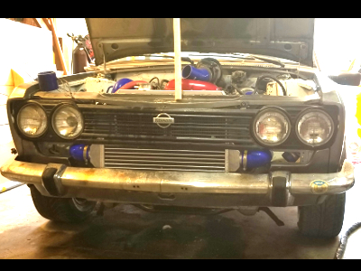
Anyhow, I've done quite a bit on the 510 lately. Between upgrading all of my brakes (discs all around), fabbed up new intercooler plumbing, and finally dumping the R33 skyline gauge cluster, I decided that the next major project to tackle would be the big electronic project: the Arduino/Raspberry Pi telemetry and custom gauge cluster system. It doesn't sound like much, since I haven't seen many overly complex Arduino or rPi builds, but this has been a pretty significant undertaking.
The basic premise of this project is this:
Use the Arduino to pull data from no less than 16 sources. On a standard Arduino UNO, this is not possible; there are only 6 analog inputs. However, using the magic of multiplexing, there's a way to quickly poll multiple sources over a single analog input; with two 8-channel multiplexers, we get that 16, plus the remaining 4 on the board itself.
Once the data is pulled (either direct 0-5v values or values drawn from a voltage divider circuit), it is neatly organized into a (name:value) pair, and sent as plain-text serial data via USB into the Raspberry Pi. On the rPI, I'm using Perl/Tk to pull in that serial data and display it graphically on a custom instrument cluster as well as saving the data for future analysis.
And then all of that is displayed on a 9x5" LCD screen.
Easy, right? Well, then there's the whole project of packaging it all up. So, that's where the 3d printer comes in. I assembled an ANET-A8 3d printer, learned how to use Blender, and printed out some bits to bring it all together.
The first thing I needed to print was an enclosure for the LCD driver. It came as a PCB board attached to the LCD screen with a power supply line and a ribbon cable; boxing it up meant printing a custom enclosure that I found and modified on thingiverse.
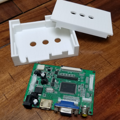
The model online didn't include a lid, so I used Blender to build one.
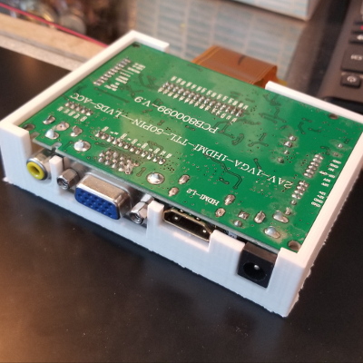
Fits like a glove.
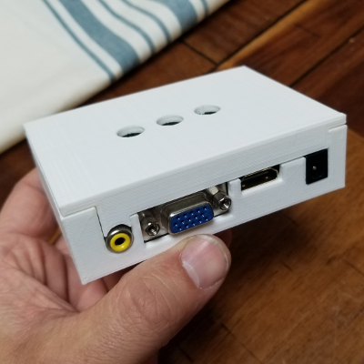
Perfect!
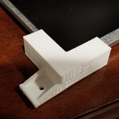
The next thing I needed to do was to figure out a way to mount the LCD. It's going to sit in the Datsun 510, so I can't just have it sitting on the dash. I printed these corner brackets, and they seem to work just fine. It's not beautiful, but it is very functional.
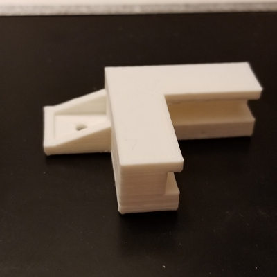
Again, using blender to design it. I've used the bracket in several of my 3d prints, as it's perfect for small screws.
Fits the LCD screen. It's a little loose, but maybe I'm compensating for heat distortion?
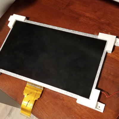
Test fit.
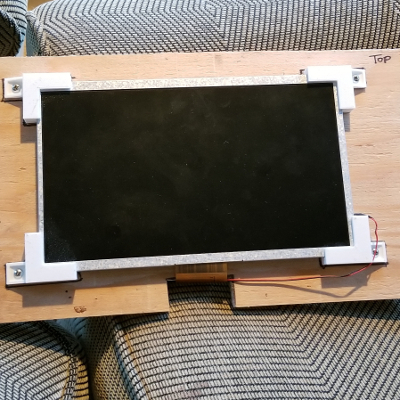
And screwed down to a piece of plywood.
The next project was to build a custom Arduino. Yes, you read that correctly. Because I have a need to take things apart and put them back together, I wanted to do one of those custom "minimalist Arduino" projects where I just use the atmega chip, a few resistors, a crystal, and some capacitors, and voila - homemade Arduino.
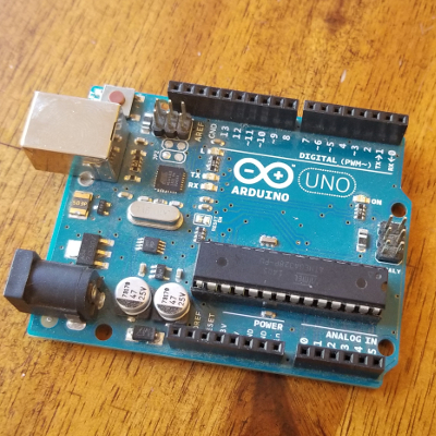
Here's an UNO. It's the one I used to test all of my code.
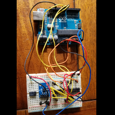
And here's the Arduino connected to the two 5041 multiplexers.
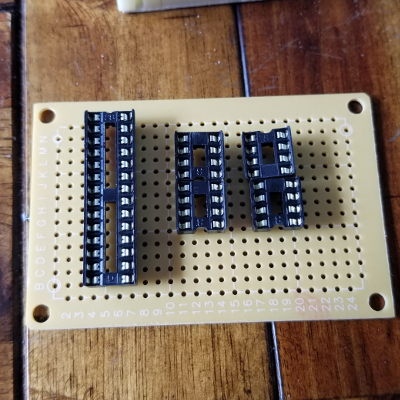
Perf board with the chip plugs. Always use these things; soldering down (and then trying to remove) a chip sucks if you have to re-orient later.
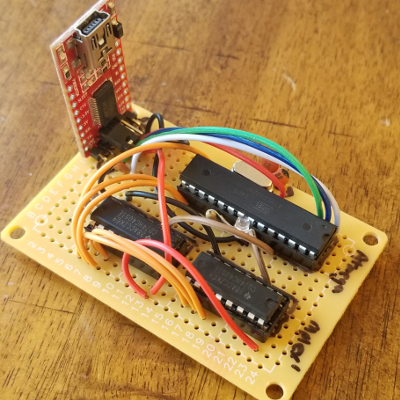
Here is my minimalist Arduino board, together with the two multiplexers and a USB interface board.
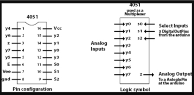
In case you're nerdy, here's the multiplexer pintout.
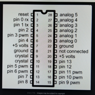
And here's the Arduino atmega chip pinout.
With 16 inputs, I didn't want a bunch of loose wires everywhere, so I decided to use some JST clips to organize my wiring. I couldn't find any 16-terminal JST plugs, so figured having 4 sets of 4 would work just fine.
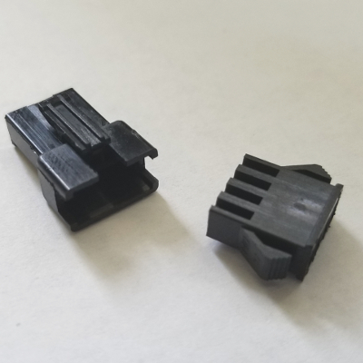
This is a 4-wire JST clip set.
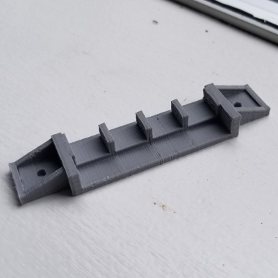
Not satisfied with having the clips dangling about, I did some test printing and built a holster for the clips.
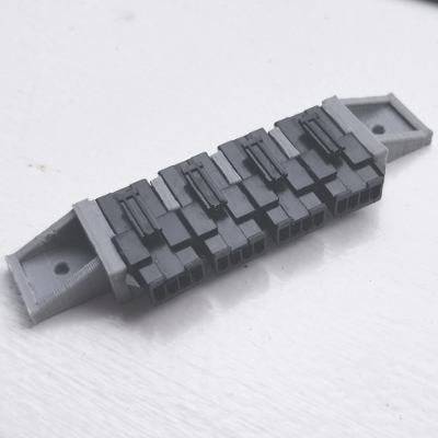
Perfect fit! However, this holster was just a proof-of-concept. I wanted to make sure they would fit properly so I can build an Arduino housing model that would incorporate the design.
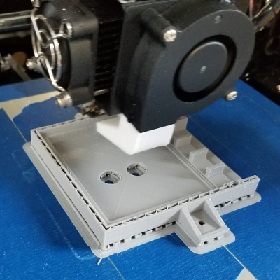
And here's a shot of the prototype of the Arduino housing. You can see the brackets that I've reused from the LCD clips, as well as the JST holster.
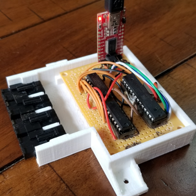
And the arduino+multiplexer perf board fits perfectly.
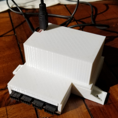
And here's a tall lid for the enclosure. In hindsight, I probably should have found a USB connector that could lay horizontally so I didn't have to make the box so tall.
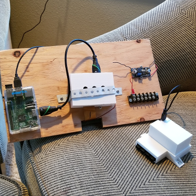
At the time of this writing, I'm still trying to figure out how to pull it all together neatly. Right now, I've just thrown it all onto a piece of plywood. It works, but this is not likely the final product.
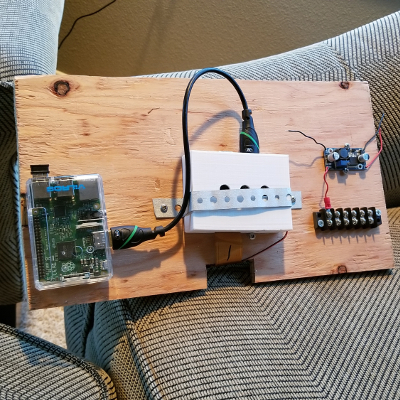
On the left is the Raspberry Pi, connected by HDMI to the LCD driver housing in the center. On the right is another project - it's going to be the power supply for the whole thing. The LCD screen requires a 12v power supply - no problem. The Datsun 510, like most cars, has a 12v battery. I'll need to include a voltage regulator circuit to address voltage spikes and reversals, since that'll destroy my electronics. The Arduino and the rPi, on the other hand, only need 5 volts, so I have a switching converter to create a 5v power supply. This is particularly useful because several of my sensors need a 5v source as well: the MAP sensor (boost sensor), for example. The Arduino also accepts 0 to 5 volt inputs, so building voltage divider circuits from here is also important.
Here, I have the Arduino hooked up and ready to go.
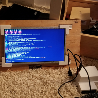
The Raspberry Pi is loading...
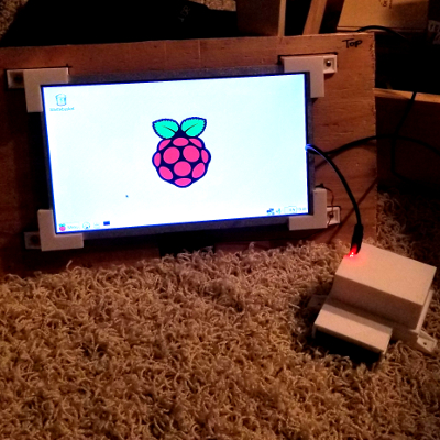
And we're in X-Windows on the Raspberry Pi.
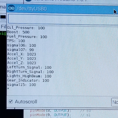
And here's the Arduino IDE serial monitor, and it's correctly reading the values from the rPi and multiplexers. There's no sensor data at the moment, so all the inputs read high. They would read low if they were grounded, and they would read correctly if they were connected to sensors properly.
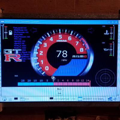
And lastly, here's the custom gauge cluster I coded. The tachometer is from an image of a Nissan Skyline tach; the Fuel Level, Oil Pressure, and Water Temp gauges were just cobbled together from some generic images online. I drew up the Boost gauge, and it may change to fit the scheme better. Once I have some data coming in from my accelerometer, I'll have the "g-force meter" working properly as well. This is all done within Perl/Tk.
I ended up using a different virtual gauge cluster for the next phase of the proof-of-concept, and it turned out quite well! It turns out that Chromium has a serial-communication plugin that works perfectly, and I was able to code this in javascript. Not that I prefer javascript over perl, but it is a little more intuitive.
End note: Due to wanting to simply drive the car and to get things done, I've changed directions on this project. However, I learned a lot during the coding and wiring, and I've applied some of the learnings to future projects.

